







Cable-stayed bridges are among the most recognisable and efficient long-span bridge structures in modern civil engineering. Their characteristic inclined cables connect the bridge deck directly to one or more pylons, creating a structural system in which the deck, stay cables and pylons work together to carry loads safely to the foundations.
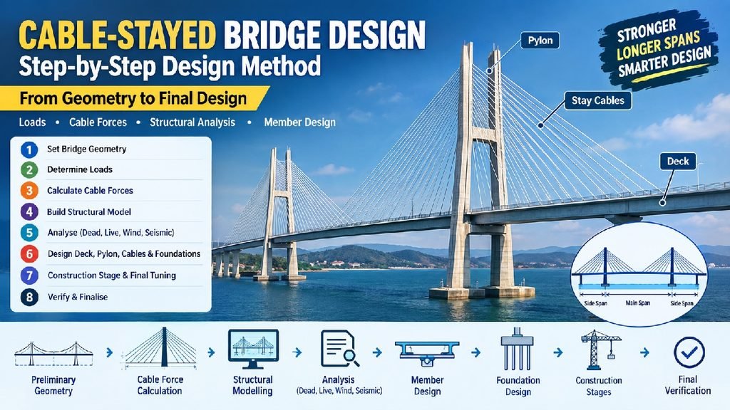
Unlike a conventional girder bridge, where the deck carries most of the bending forces, a cable-stayed bridge transfers a significant portion of the deck load through the stay cables to the pylons. This allows engineers to achieve longer spans while maintaining a relatively slender deck.
Designing a cable-stayed bridge, however, requires much more than simply selecting cable sizes. The engineer must establish the bridge geometry, determine cable forces, design the deck and pylons, consider nonlinear behaviour, analyse construction stages and check the structure under traffic, wind, temperature and seismic actions.
This article presents a practical step-by-step method for cable-stayed bridge design, including preliminary sizing, cable-force calculations, structural modelling and major design checks.
1. What Is a Cable-Stayed Bridge?
A cable-stayed bridge generally consists of three primary structural components:
- Deck
- Pylon or tower
- Stay cables
The stay cables are connected between the deck and pylons. The cables transfer vertical loads from the deck to the pylons, while the pylons transfer these forces to the foundations.
The basic load-transfer mechanism can be understood as:
Traffic/Dead Load → Deck → Stay Cables → Pylon → Foundation → Ground
The cable forces also introduce horizontal components into the deck. These horizontal components produce compression in the deck and are an important part of cable-stayed bridge behaviour.
2. Why Are Cable-Stayed Bridges Used?
Cable-stayed bridges are particularly attractive when a project requires a relatively long main span but a suspension bridge is unnecessary or uneconomical.
Some important advantages are:
- Efficient load-carrying system
- Long main-span capability
- Relatively shallow deck
- Attractive architectural appearance
- Good structural stiffness
- Suitable for free-cantilever construction
- Efficient use of high-strength cables
- Possibility of controlling deck forces through cable stressing
However, the system is also highly sensitive to:
- Cable stiffness
- Cable geometry
- Pylon stiffness
- Deck stiffness
- Construction sequence
- Temperature
- Wind
- Cable force variation
- Differential support movement
Therefore, cable-stayed bridges normally require a detailed structural analysis rather than a simple static calculation.
3. Main Components of a Cable-Stayed Bridge
3.1 Deck
The deck carries:
- Self-weight
- Wearing course
- Traffic loads
- Pedestrian loads where applicable
- Wind loads
- Temperature effects
- Construction loads
The deck can be constructed using reinforced concrete, prestressed concrete, structural steel or a composite system.
One of the major advantages of the cable system is that the deck can be significantly shallower than a conventional long-span girder.
3.2 Pylon
The pylon is the main vertical structural element supporting the stay cables.
It transfers the vertical components of cable forces toward the foundation.
Depending on the bridge arrangement, pylons can have different shapes, such as:
- Single vertical tower
- Twin vertical towers
- A-shaped tower
- H-shaped tower
- Inverted-Y tower
The pylon also provides lateral stability to the bridge system.
3.3 Stay Cables
Stay cables provide direct support to the deck.
Depending on the bridge geometry, the cables may be arranged as:
Fan arrangement
The cables converge toward a relatively small region near the top of the pylon.
Harp arrangement
The cables are approximately parallel to each other.
Semi-fan arrangement
This is a combination of the fan and harp arrangements and is widely useful from both structural and architectural perspectives.
4. Preliminary Bridge Geometry
Before starting the detailed analysis, the engineer must establish the preliminary geometry.
For a typical three-span cable-stayed bridge:
Side Span + Main Span + Side Span
The main span is usually significantly longer than the side spans.
The source material indicates that side spans of approximately 40% of the main span can be considered as a useful preliminary arrangement, although the final ratio depends on the complete structural system and project requirements.
For example, if:
Main span = 300 m
then an initial side-span estimate could be:
Side span ≈ 0.40 × 300 = 120 m
Therefore:
120 m + 300 m + 120 m
would be a reasonable preliminary geometry for study.
This is only a preliminary proportion and should not be treated as a mandatory design requirement.
5. Preliminary Pylon Height
Pylon height is one of the most important parameters affecting cable inclination and cable forces.
A useful preliminary proportion mentioned in the source material is:
Pylon height above deck / Main span ≈ 1/5
Therefore, for:
Main span = 300 m
a preliminary pylon height above the deck could be:
300/5 = 60 m
The actual pylon height must subsequently be optimized based on:
- Cable angle
- Cable forces
- Deck forces
- Pylon forces
- Architectural requirements
- Wind behaviour
- Construction requirements
6. Cable Spacing
Cable spacing determines how much deck load is transferred to each stay cable.
For preliminary design, cable spacing of approximately:
5–8 m
can be considered based on the source material.
Smaller cable spacing generally provides a more uniform support to the deck and can reduce local deck bending.
However, increasing the number of cables also increases:
- Anchorage requirements
- Cable protection requirements
- Construction complexity
- Inspection and maintenance requirements
Therefore, cable spacing should be optimized rather than selected solely on structural grounds.
7. Preliminary Deck Depth
The deck depth is influenced by:
- Main span
- Traffic loading
- Cable arrangement
- Deck stiffness
- Torsional requirements
- Construction method
The source material indicates a preliminary deck span-to-depth ratio of approximately:
L / D ≈ 250
where:
- L = relevant span
- D = deck depth
For example, if a preliminary span of 300 m were directly used:
D ≈ 300/250 = 1.20 m
However, this should only be treated as an initial estimate. The final deck depth depends strongly on the actual bridge system and should be established through structural analysis.
8. Determine the Design Loads
The next step is to establish all loads acting on the bridge.
These normally include:
Permanent loads
- Deck self-weight
- Wearing course
- Kerbs
- Crash barriers
- Utilities
- Drainage systems
- Cable self-weight
- Pylon self-weight
- Other permanent components
Variable loads
- Vehicular live load
- Pedestrian load
- Braking and acceleration
- Centrifugal forces
- Other traffic-related actions
Environmental loads
- Wind
- Temperature
- Earthquake
- Seismic effects
- Water/current effects where applicable
Construction loads
- Form travellers
- Temporary supports
- Construction equipment
- Segment loads
- Temporary cable forces
The governing bridge code and project specifications must be used for the final load values and combinations.
9. Establish Stay Cable Geometry
For every stay cable, determine:
- Deck anchorage coordinate
- Pylon anchorage coordinate
- Horizontal projection
- Vertical difference
- Cable length
- Cable inclination
The cable angle can be calculated approximately as:
where:
- θ = cable inclination
- Δz = vertical difference between deck and pylon anchorage
- Δx = horizontal projection
Cable length can be estimated as:
These values are required for calculating preliminary cable forces.
10. Preliminary Cable Force Calculation
One of the most important preliminary calculations is determining the force in each stay cable.
Suppose:
- Deck load = w kN/m
- Cable spacing = s m
The approximate tributary load carried by one cable is:
The vertical component of cable force must approximately balance this load:
Therefore:
where:
- T = cable tension
- Wi = tributary vertical load
- θ = cable inclination
The horizontal component is:
or:
This horizontal component introduces compression into the deck.
11. Example Cable Force Calculation
Consider a preliminary cable with:
Deck load:
Cable spacing:
Therefore:
Assume:
The approximate cable tension is:
The vertical component is:
The horizontal component is:
Therefore, a cable carrying approximately 600 kN of vertical load at an inclination of 30° would have a preliminary tension of about 1200 kN.
This is a preliminary hand calculation. It is not the final cable force because the actual force depends on the complete structural system, stiffness, prestressing, construction sequence and load combinations.
12. Why Cable Angle Is Important
The cable angle has a major effect on cable tension.
From:
it can be seen that a flatter cable produces a higher tension for the same vertical load.
For example, if:
then:
At 30°
At 45°
Therefore, increasing the cable angle can substantially reduce the cable tension.
However, cable geometry cannot be selected based only on cable force. Pylon height, deck compression, architectural constraints and construction requirements must also be considered.
13. Initial Cable Prestressing
A cable-stayed bridge is normally not simply constructed and then loaded.
The stay cables are stressed during construction to achieve the desired structural geometry and force distribution.
The initial cable force may be selected to:
- Control deck deflection
- Reduce bending moments
- Maintain the desired deck profile
- Control pylon deformation
- Balance permanent loads
- Achieve the target construction geometry
This makes cable-stayed bridge design an iterative process.
The engineer selects an initial cable force, analyses the bridge, checks the resulting geometry and forces, and then adjusts the cable forces.
14. Important Concept: Pylon Balance
Under permanent loading, the horizontal components of the main-span and backstay cable forces should be reasonably balanced.
The main-span cables generate horizontal forces toward the main span, while the backstays provide balancing forces in the opposite direction.
A simplified conceptual condition is:
When these forces are properly balanced, unnecessary bending of the pylon can be reduced.
This is one of the key principles behind cable-stayed bridge design.
15. Structural Modelling
After preliminary calculations, the bridge is developed into a structural analysis model.
A simplified global model can contain:
- Beam elements for deck
- Beam elements for pylons
- Beam elements for piers
- Cable/truss elements for stay cables
- Appropriate supports
- Pylon-deck connections
- Cable anchorage locations
For preliminary studies, a line-element model is often sufficient.
For detailed local investigations, shell or solid finite elements may be required.
16. 2D or 3D Model?
A 2D model can be useful when:
- The bridge has a single cable plane
- Loading is primarily symmetrical
- Only vertical global behaviour is being studied
However, a 3D model is generally required for realistic assessment of a bridge with two cable planes, especially when considering:
- Torsion
- Eccentric traffic loading
- Wind
- Seismic loading
- Differential effects
- Lateral behaviour
Therefore, a practical design workflow is often:
2D preliminary model → 3D global model → detailed local FE model
17. Cable Nonlinearity
Stay cables are not always adequately represented by simple linear truss behaviour.
Important nonlinear effects include:
- Large displacement
- Cable sag
- Geometric stiffness
- P-Delta effects
- Interaction between cable force and structural deformation
Cable sag can become important for sufficiently long cables.
For preliminary models, simplified cable behaviour may be acceptable, but the final analysis should use an appropriate cable formulation based on the project requirements and governing design standards.
18. Dead Load Analysis
The first major analysis stage is the permanent-load analysis.
Apply:
- Deck self-weight
- Pylon self-weight
- Cable self-weight
- Wearing course
- Barriers
- Utilities
- Other permanent loads
The engineer should review:
- Deck bending moments
- Deck axial force
- Deck shear
- Cable forces
- Pylon axial forces
- Pylon bending moments
- Vertical displacement
- Horizontal displacement
The dead-load analysis is particularly important because it establishes the basic equilibrium of the cable-stayed system.
19. Live Load Analysis
Traffic loading should be placed at critical positions.
Unlike a conventional bridge, where critical live-load positions can sometimes be identified relatively easily, cable-stayed bridges have a highly interactive structural system.
Different live-load arrangements can produce critical:
- Deck bending
- Deck axial force
- Cable stress
- Pylon bending
- Pylon shear
- Torsion
Therefore, multiple load positions and combinations should be investigated.
20. Deck Design
The deck is subjected to a combination of:
- Bending
- Shear
- Axial compression
- Torsion
- Local effects around cable anchorages
The horizontal components of cable forces introduce significant axial compression into the deck.
The deck design should therefore consider combined:
where:
- N = axial force
- M = bending moment
- V = shear force
- T = torsion
The final reinforcement or steel section is selected after obtaining the governing envelopes from the global analysis.
21. Pylon Design
The pylon primarily receives the vertical components of the stay cable forces.
A preliminary estimate of the pylon axial load can be expressed as:
where:
The pylon must be checked for:
- Axial compression
- Bending
- Shear
- Buckling
- P-Delta effects
- Construction-stage forces
- Wind
- Seismic effects
- Local stresses near cable anchorages
For reinforced concrete pylons, second-order effects can be particularly important because of the large axial compression.
22. P-Delta Analysis
A cable-stayed pylon can carry very large axial compression.
If the pylon deflects laterally, the axial load produces an additional moment.
Conceptually:
where:
- M1 = first-order moment
- N = axial force
- Δ = lateral displacement
- M2 = second-order moment
This is commonly referred to as the P-Delta effect.
For tall and slender pylons, second-order analysis should therefore be properly considered.
23. Stay Cable Design
Cable design must satisfy several requirements.
Important checks include:
Ultimate limit state
The cable must have adequate resistance against the governing ultimate tension.
Serviceability
Cable stress and bridge deformation must remain within applicable limits.
Fatigue
Repeated traffic loading produces variations in cable stress.
The stress range is:
Fatigue can become one of the governing considerations for stay cables.
Constructability
The cable must be installable, adjustable and properly anchored.
Replaceability
Modern cable-stayed bridge systems should consider inspection, maintenance and eventual cable replacement.
The exact allowable cable stresses and fatigue criteria must be taken from the governing bridge/cable design standard and project specifications rather than applying a generic percentage of ultimate tensile strength.
24. Cable Anchorage Design
Cable forces are transferred into the deck and pylon through anchorage systems.
The anchorage region can experience:
- High concentrated forces
- Local compression
- Bursting stresses
- Splitting stresses
- Local bending
- Shear stresses
Therefore, the anchorage zone often requires detailed finite-element investigation.
A global beam model alone may not adequately represent these local effects.
25. Foundation Design
The pylon transfers large forces to the foundation.
The foundation design must consider:
- Vertical compression
- Horizontal forces
- Bending moments
- Uplift where applicable
- Seismic effects
- Soil stiffness
- Settlement
- Differential settlement
- Pile capacity
- Group effects
- Lateral pile behaviour
For large cable-stayed bridges, deep foundations such as pile foundations are commonly investigated.
The foundation must be designed using the governing geotechnical and structural design criteria.
26. Construction Stage Analysis
Construction-stage analysis is one of the most important aspects of cable-stayed bridge design.
A bridge that is safe in the final configuration may experience critical forces during construction.
Typical construction stages include:
- Construction of foundations
- Construction of piers
- Construction of pylons
- Construction of initial deck segments
- Installation of stay cables
- Cantilever deck construction
- Cable stressing
- Deck closure
- Final cable adjustment
- Application of permanent loads
At every stage, the engineer should monitor:
- Cable forces
- Deck displacement
- Pylon displacement
- Pylon stresses
- Construction reactions
27. Final Cable Tuning
After constructing the complete analytical model, the initial cable forces are adjusted.
The objective is generally to achieve the desired:
- Deck profile
- Pylon geometry
- Permanent-load bending moment distribution
- Cable-force distribution
- Support reactions
This process is usually iterative.
A simplified workflow is:
Assume cable forces → Analyse → Check geometry → Adjust cable forces → Analyse again
The process continues until the desired equilibrium state is achieved.
28. Temperature Effects
Cable-stayed bridges are sensitive to temperature because different structural components can experience different temperature changes.
Temperature analysis should consider:
- Uniform temperature change
- Temperature gradients
- Differential temperature
- Cable temperature
- Deck temperature
- Pylon temperature
Temperature effects can significantly change:
- Cable tension
- Deck displacement
- Pylon forces
- Support reactions
29. Wind Analysis
Because cable-stayed bridges are flexible structures with large exposed surfaces, wind analysis is important.
The analysis may include:
- Static wind load
- Gust effects
- Wind-induced vibration
- Cable vibration
- Deck aerodynamic stability
- Pylon aerodynamic effects
For long-span bridges, aerodynamic and wind-tunnel studies may be required depending on the bridge size and governing standards.
30. Seismic Analysis
For bridges located in seismic regions, seismic analysis should include the complete bridge system.
Important components include:
- Mass distribution
- Pylon stiffness
- Deck stiffness
- Cable stiffness
- Pier stiffness
- Foundation flexibility where applicable
- Damping
- Soil-structure interaction where required
Typical analysis methods may include:
Modal analysis
Used to determine:
- Natural frequencies
- Mode shapes
- Effective modal mass
Response spectrum analysis
Used to evaluate structural response under the prescribed seismic spectrum.
Time-history analysis
May be required for more advanced studies or when specified by the design criteria.
Seismic load combinations should be established according to the governing bridge seismic provisions.
31. Cable Forces Under Seismic Loading
Cable forces can vary significantly during seismic excitation.
Therefore, the engineer should review:
and
for critical combinations.
The analysis should ensure that cables remain within the applicable design limits and that excessive deformation does not occur.
32. Typical Design Workflow
The complete cable-stayed bridge design process can be summarized as follows:
Step 1: Collect project requirements
↓
Step 2: Select bridge arrangement
↓
Step 3: Determine main and side spans
↓
Step 4: Select pylon locations
↓
Step 5: Determine preliminary pylon height
↓
Step 6: Select cable arrangement
↓
Step 7: Select cable spacing
↓
Step 8: Estimate deck depth
↓
Step 9: Calculate permanent loads
↓
Step 10: Calculate traffic and environmental loads
↓
Step 11: Establish cable geometry
↓
Step 12: Calculate preliminary cable forces
↓
Step 13: Estimate initial cable prestressing
↓
Step 14: Develop the global structural model
↓
Step 15: Perform dead-load analysis
↓
Step 16: Adjust cable forces
↓
Step 17: Perform live-load analysis
↓
Step 18: Design the deck
↓
Step 19: Design the pylon
↓
Step 20: Design the stay cables
↓
Step 21: Design cable anchorages
↓
Step 22: Design piers and foundations
↓
Step 23: Perform construction-stage analysis
↓
Step 24: Check P-Delta and nonlinear effects
↓
Step 25: Perform temperature and wind analysis
↓
Step 26: Perform seismic analysis
↓
Step 27: Generate final force envelopes
↓
Step 28: Complete reinforcement/detailing
↓
Step 29: Final design verification
33. Cable-Stayed Bridge Design: Important Equations
For quick reference, some preliminary equations are given below.
Cable angle
Cable length
Tributary load
Preliminary cable tension
Vertical cable component
Horizontal cable component
Approximate pylon axial force
Cable stress
Stress range
Second-order moment
These equations are useful for preliminary design and checking, but the final design should be based on the complete structural analysis and the applicable design standards.
34. STAAD.Pro or MIDAS Civil Modelling Approach
For engineers working with software such as STAAD.Pro or MIDAS Civil, a practical modelling sequence is:
Step 1 — Create geometry
Define:
- Deck nodes
- Pylon nodes
- Pier nodes
- Cable anchorage nodes
Step 2 — Define structural members
Create:
- Deck beam elements
- Pylon beam elements
- Pier elements
Step 3 — Define stay cables
Use appropriate cable/truss elements and ensure that their stiffness and nonlinear behaviour are represented appropriately.
Step 4 — Define supports
Model:
- Foundation restraints
- Bearings
- Expansion conditions
- Lateral restraints
according to the actual bridge structural system.
Step 5 — Apply self-weight
Include the weight of:
- Deck
- Pylon
- Piers
- Cables
Step 6 — Apply cable prestressing
Initial cable forces should be introduced according to the selected construction-stage methodology.
Step 7 — Run construction stages
Activate structural components in the actual construction sequence.
Step 8 — Apply traffic loading
Run the required traffic load positions and combinations.
Step 9 — Apply wind and temperature
Include appropriate environmental actions.
Step 10 — Perform seismic analysis
Use the required modal and seismic analysis procedures.
Step 11 — Extract design envelopes
Review:
- Deck N
- Deck M
- Deck V
- Deck T
- Pylon N
- Pylon M
- Pylon V
- Cable forces
- Support reactions
- Displacements
35. Common Mistakes in Cable-Stayed Bridge Design
Several mistakes can lead to unrealistic results.
Mistake 1: Designing cables independently
Cable force cannot be finalized without considering the deck-pylon-cable interaction.
Mistake 2: Ignoring construction stages
The final structure is not the only condition that needs to be checked.
Mistake 3: Using only a 2D model
A 2D model may not capture torsion and asymmetric effects in a bridge with two cable planes.
Mistake 4: Ignoring cable sag
For sufficiently long cables, sag can affect cable stiffness and structural response.
Mistake 5: Ignoring P-Delta
Tall pylons carrying large compression can develop significant second-order effects.
Mistake 6: Checking only maximum cable tension
Cable fatigue depends strongly on stress variation, not just maximum force.
Mistake 7: Ignoring anchorage-zone stresses
Local cable anchorage forces can be much more concentrated than the global beam model indicates.
Mistake 8: Treating preliminary equations as final design
The simple cable-force equation is excellent for preliminary sizing, but the final force must come from the complete structural system.
36. What Makes Cable-Stayed Bridge Design Different?
The most important difference between a cable-stayed bridge and a conventional bridge is that the structural system can be actively controlled through cable forces.
The engineer does not simply calculate loads and design members.
Instead, the design becomes an iterative process:
Geometry → Cable Forces → Structural Response → Cable Adjustment → Structural Response → Final Equilibrium
This interaction between analysis, geometry and construction is what makes cable-stayed bridge design both challenging and interesting.
37. Final Checklist for Cable-Stayed Bridge Design
Before finalizing the design, the engineer should verify:
Geometry
- Main span
- Side spans
- Pylon height
- Cable spacing
- Cable inclination
- Deck depth
Global structural behaviour
- Dead-load response
- Live-load response
- Cable forces
- Deck N-M-V-T
- Pylon N-M-V
- Deflections
Cable design
- Maximum tension
- Minimum tension
- Stress range
- Fatigue
- Cable stiffness
- Cable sag
- Anchorage
Pylon
- Axial compression
- Bending
- Shear
- Buckling
- P-Delta
- Wind
- Seismic
Deck
- Flexure
- Shear
- Axial force
- Torsion
- Local anchorage effects
- Serviceability
Foundation
- Vertical capacity
- Lateral capacity
- Moment
- Settlement
- Seismic effects
Construction
- Construction stages
- Temporary conditions
- Cable stressing sequence
- Deck closure
- Final cable tuning
Conclusion
The design of a cable-stayed bridge is a combination of structural mechanics, cable engineering, finite-element analysis and construction-stage control.
The three major components—the deck, pylon and stay cables—must be designed as one integrated structural system.
The preliminary design can begin with relatively simple relationships such as:
and
to estimate cable forces. However, the final cable forces and structural member forces should be obtained through an appropriate global analysis that accounts for structural stiffness, cable behaviour, construction stages and the required load combinations.
A reliable design workflow therefore follows:
Preliminary geometry → Preliminary cable forces → Initial prestressing → Global FEM model → Construction-stage analysis → Cable adjustment → Final load analysis → Member design → Foundation design → Final verification
For an actual bridge project, the numerical values, load combinations, allowable stresses, fatigue criteria and detailing requirements must always be taken from the applicable bridge design codes, project specifications and approved design basis.
The PDFs used for this article emphasize the same central principle: a cable-stayed bridge should be treated as an integrated deck–cable–pylon system, rather than as three independently designed components.