







Minimum Reinforcement
- The minimum reinforcement in walls, floors and roofs in each of two directions at right angles, within each surface zone, shall not be less than the percentage specified in Table 5. The percentage applies to surface zones, as shown in Fig. 1 and Fig. 2.
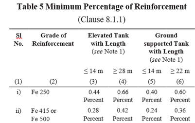
NOTE:
- Length is the horizontal length of continuous reinforced concrete members between full movement joints (if provided) or the end of the structure along the direction of main reinforcement. For significantly long lengths (> 30 m), a higher percentage of steel may be required.
- For lengths between 14 m and 28 m for elevated tanks, and between 14 m and 22 m for ground supported tanks, minimum percentage of reinforcement required shall be linearly interpolated.
In walls having thickness less than 160 mm or slabs having thickness less than 180 mm, the entire minimum reinforcement may be placed in one face.
For ground slabs having thickness less than 300 mm (see Fig. 2), the calculated reinforcement should be placed wholly in the top surface with cover not exceeding 50 mm. For ground slabs having thickness more than 300 mm, the reinforcement required shall be calculated separately for top and surface zone as per Annex A and shall be placed accordingly with cover not exceeding 50 mm.
Size of Bars, Distance between Bars, Laps and Bends
- Size of bars, distance between bars, laps and bends in bars, and fixing of bars shall be in accordance with IS 456. Spacing of bars should be as small as possible, without causing congestion of steel and difficulty in placing and vibrating concrete.
- Laps in the horizontal bars of wall or longitudinal bars of beam which can have a single concrete pour of 300 mm or more below the bar shall be provided
1.4 times the calculated lap length. In members subjected to axial tension or hoop, the bars in direct tension shall be provided with lap double that of the calculated lap length.
- Bar spacing shall not exceed 300 mm or the thickness of the section, whichever is less.
Junction of Members
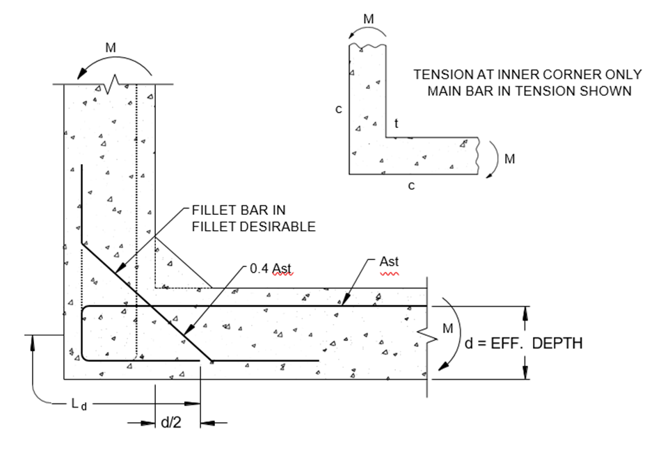
Where any two members, such as wall and slab, are connected monolithically at a right-angled junction and subjected to moments, shears and axial force which tend to open it (that is, the inner faces of the plates are in tension at the corner), proper detailing of the reinforcement shall be ensured to cater for the diagonal tension forces. Detailing should be as shown in Fig. 3 or the junction may be designed by an appropriate strut and tie model.

Structural Design Specification: Reinforced Concrete Liquid-Retaining Facilities
1. General Provisions and Regulatory Scope
In hydraulic infrastructure, structural stability is a baseline requirement, but the governing strategic objective is long-term impermeability. Generic reinforced concrete codes, such as IS 456, are insufficient for these applications as they do not account for the specific serviceability demands of liquid containment. The adoption of IS 3370:2021 is mandatory to transition from “strength-only” design to a methodology that prioritizes crack control and durability. Failure to adhere to these specialized standards typically results in post-commissioning leakage, where remedial costs are estimated at 5 to 20 times the initial construction expenditure.
These specifications define the requirements for the following primary application domains:
- Water-Supply Infrastructure: Ground-level reservoirs (GLSR), elevated service reservoirs (ESR/OHT), and underground sumps.
- Environmental Engineering: Sewage Treatment Plants (STP) and Effluent Treatment Plants (ETP) basins, including aeration tanks and clarifiers.
- Industrial Containment: Fire-water reservoirs, cooling-tower basins, and process liquid tanks.
The shift from the legacy 1965 standard to the modern 2021 edition is summarized below:
| Feature | Legacy IS 3370:1965 | Modern IS 3370:2021 |
| Design Philosophy | Working Stress Method (WSM) | Limit State Method (LSM) / WSM |
| Primary Goal | Resistance to cracking via low stress | Controlled crack widths (Serviceability) |
| Min. Concrete Grade | M20 | M30 |
| Durability Approach | Indirect (Low permissible stresses) | Direct (w/c ratio, cover, cement content) |
| Concrete Condition | Assumed Uncracked | Calculated Crack Width Limits |
2. Material Performance and Mix Design Parameters
The site engineer shall ensure the concrete mix is engineered for low permeability rather than simple compressive strength. Under “Severe” exposure conditions—defined by continuous liquid contact and wetting/drying cycles—the concrete matrix must be dense enough to resist capillary action.
All RCC liquid-retaining structures shall adhere to the following mix parameters derived from IS 3370:2021:
- Minimum Concrete Grade: M30 for RCC.
- Maximum Free Water-Cement (w/c) Ratio: 0.45. This limit is non-negotiable to minimize interconnected pores.
- Minimum Cement Content: 320 kg/m³.
- Maximum Cement Content: 450 kg/m³ for standard sections; 350 kg/m³ for mass concrete.
Mass Concrete Specifications (Sections >1000 mm)
For heavy reservoir walls or mat foundations exceeding 1m in thickness, the engineer shall implement thermal control measures to mitigate heat-of-hydration cracking:
- SCM Replacement: 25% to 35% Fly Ash replacement of OPC is mandatory.
- Cement Selection: Use of low-heat cement (IS 12330) is required.
- Thermal Gradient: Cooling of mixing water or formwork insulation may be required to prevent differential temperature cracks.
Curing Mandate: A curing log shall be maintained verifying continuous moist curing for 14 to 21 days. Terminating curing at 7 days is a major cause of surface micro-cracking and is strictly prohibited.
3. Structural Design and Crack Width Control
The Serviceability Limit State (SLS) of cracking governs the design of these facilities. Strength-only designs per IS 456 often lead to seepage because they permit crack widths up to 0.3 mm. For liquid retention, the following limits shall be strictly observed:
| Face Category | Exposure Type | Max Calculated Crack Width |
| Liquid Face (Contact) | Severe | 0.1 mm |
| Non-Liquid Face | Moderate | 0.3 mm |
Design Methodology: Engineers shall utilise a Modular Ratio (m) of 9.33 for M30 concrete. To achieve the 0.1 mm limit, the design shall prioritise a high number of small-diameter bars at close spacing rather than fewer large-diameter bars. This detailing optimises crack distribution. Reliance on “self-healing” of cracks—a 1965-era fallacy—is not permitted for modern infrastructure; zero-leakage must be achieved through structural detailing and mix density.
4. Reinforcement and Cover Specifications
The “Surface Zone” reinforcement is the primary defence against early thermal and drying shrinkage. Minimum reinforcement percentages are more stringent than those in IS 456 and are based on section thickness:
| Member Thickness | Min. Reinforcement % (Each Face, Each Direction) |
| 100 mm | 0.30 % |
| 250 mm | 0.25 % (Interpolated) |
| 500 mm or more | 0.20 % |
Detailing Directives:
- Two-Way Loading: Reinforcement shall be distributed equally on both faces, as walls must resist both internal hydrostatic pressure and external soil/atmospheric loads.
- Nominal Cover: A minimum nominal cover of 45 mm shall be provided to all reinforcement on the liquid face to protect against corrosion during alternate wetting and drying.
5. Movement and Construction Joint Engineering
Joints are the most frequent failure points. They must be strategically placed to manage volumetric changes without inducing uncontrolled fissures.
- Spacing: Full movement joints shall not exceed 7.5 m intervals. Partial joints/contraction joints shall be placed at a maximum of 15 m.
- Profile Selection: Dumbbell waterstops shall be used for construction joints; Centre Bulb profiles are mandatory for expansion joints to accommodate lateral movement.
Technical Directive: Sinecos PVC Waterstop Installation
- Marking: Identify the joint centerline; the waterstop must be centred exactly.
- Fixing: Secure the waterstop to reinforcement using binding wire. It must be straight, untwisted, and free of bends.
- Positioning: Half the width must be embedded in the first pour; the remainder in the second.
- Welding: Use a specialised welding heater. Both ends must be heated evenly until molten before being pressed together to form a seamless bond.
- First Pour: Concrete shall be poured and vibrated to fully surround the waterstop. Warning: Do not allow high-velocity discharge to “fold over” the waterstop during the pour.
- Inspection: Verify the waterstop is intact and free of air voids/debris before the second pour.
6. Service Penetrations and Sealing Systems
Service penetrations for pipes and conduits are critical vulnerabilities. This specification follows EAD 280050-00-0605 for installations involving gas or water not intended for human consumption.
Categories of Sealing Systems
- Type 1 (Built-In): Cast into formwork. It ensures a seal against the concrete but requires a Type 3 sealing insert to seal against the actual media pipe.
- Type 2 (Add-On): Fixed over existing openings via fasteners.
- Type 3 (Sealing Insert): Annular “press seals” placed between the pipe and the opening/Type 1 sleeve.
Performance Characteristics
| Characteristic | Assessment Criteria | Acceptance |
| Axial Load | 1000 N ballast for 24 hours. | No deformation. |
| Impact Load | 4 kg gravel bag dropped from 2000 mm. | Dimensional stability. |
| Radial Load | 1200 N horizontal force at 1.2 kN/min. | Integrity maintained. |
| Watertightness | Immersion/Pressure test with colored water. | No water ingress recorded. |
Mandatory: All wall crossings shall utilise puddle flanges or wall-passage assemblies with integrated water-stop collars. Site-made mastic fixes are strictly prohibited.
7. Quality Assurance and Hydrostatic Validation
Handover is contingent upon successful completion of the Hydrostatic Leak Test per IS 3370 Part 4.
- Protocol: The structure shall be filled and allowed to stabilise for 7 to 14 days to allow for initial absorption.
- Drop Limits (Over 7 Days):
- Proportional: \le 1/500 of average depth.
- Absolute (Covered Tanks): \le 2 mm.
- Absolute (Uncovered Tanks): \le 5 mm.
Common Practitioner Mistakes
- Early Backfilling: Do not apply lateral soil pressure until 28-day strength is verified and the hydrostatic test is passed.
- Ignoring Mass Concrete: Sections >1 m failing due to thermal core-surface differentials.
- Curing Neglect: Terminating curing at 7 days, leading to high permeability.
Closing Statement: Adherence to these rigorous structural and material specifications ensures the operational longevity of the facility. The marginal 8–15% cost premium for BIS-compliant construction is a necessary investment to avoid the catastrophic lifecycle costs of a leaking structure.